




Onboard electronics refers to all electronic systems integrated into a device to ensure its operation, control, or optimization. In other words, these are electronic components (circuits, sensors, microcontrollers, software) that are distributed throughout the equipment to make it function.
The concept of embedded electronics now plays a central role in the design of modern vehicles. From engine management to active safety systems, as well as comfort features and charging systems, cars now rely on a complex network of modules, sensors, and the electrical conductors that connect them. While these systems enable enhanced performance and automation, they also come with their own set of vulnerabilities. A simple warning light on the dashboard may indicate a minor issue… or be an early warning sign of a critical failure, or even a fire. Some failures may not even be detected by the vehicle.
To better understand how an electrical anomaly can develop, it is essential to understand the system’s structure. In this article, we will discuss the basics of vehicle electronic architecture and the technical challenges associated with its failures.
Electronic Modules and Integrated Protection Devices
Modern vehicles typically contain more than 100 distinct electronic modules, each dedicated to a specific function. These include engine control units, battery controllers, braking units, climate control units, and driver-assistance systems. These modules continuously exchange data via various communication protocols, such as CAN, LIN, or Ethernet.
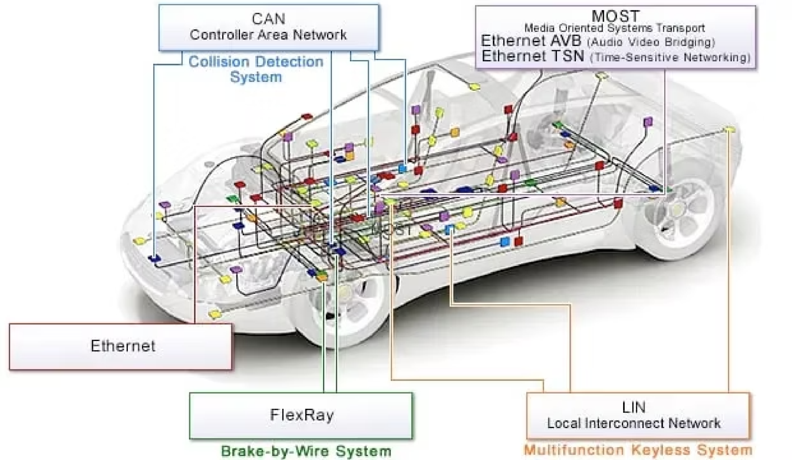
These circuits are powered by low-voltage systems, most commonly 12 V, although some newer vehicles use 48 V for accessories that consume more power. Various devices are in place to protect these systems. The most common are fuses, which have an internal filament that melts when exposed to excessive current.
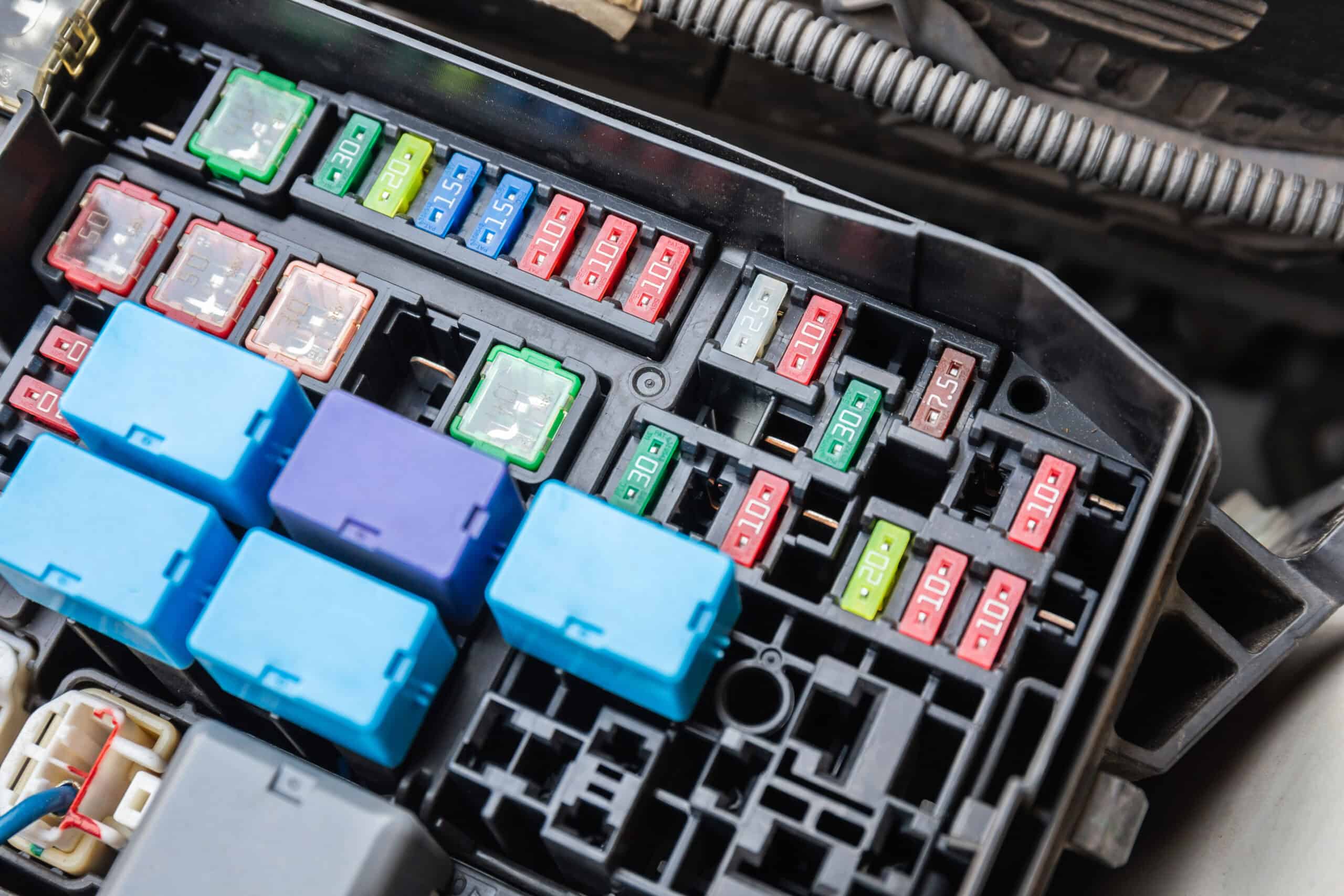
Electronic fuses, more commonly known as “e-Fuses,” are also becoming increasingly common. Unlike a conventional fuse, an e-Fuse is an electronic switch—often with automatic reset—that can respond to temperature, current, or voltage levels, as well as to more advanced parameters.

Nevertheless, despite the sophistication of the e-Fuse, an electrical circuit can still fail even when operated within the voltage, current, and temperature parameters for which it was designed. A thorough analysis of these circuits and the fuses involved is crucial for identifying modules that may have failed. We will discuss this in the next section.


The Most Common Failures and Symptoms in Automotive Circuits
Certain electrical faults are frequently encountered in repair shops. A connector that is not properly seated or is corroded can cause localized electrical resistance, leading to overheating—sometimes severe enough to melt the insulation or create an electrical arc. Similarly, a wire that is pinched or rubbing against another metal component—often after reinstalling a large component such as a bumper or the dashboard—can expose the wire to the chassis, causing a short circuit. This type of failure is sometimes accompanied by typical symptoms, such as warning lights that turn on or off randomly, electronic modules that reboot on their own, accessories that momentarily stop working (radio, headlights, windows, etc.), or unusual clicking noises from relays. As part of our investigative procedures at Origin, we are able to detect traces of electrical activity attributable to such problems. For example, we can examine a copper wire that has been welded to a sharp edge or that has been partially damaged by melting.

Water infiltration is another common cause of failure. The presence of more pronounced localized oxidation, such as verdigris, is a sign often observed during an investigation related to water infiltration. It can occur when a windshield is improperly sealed, a door seal is damaged, or a sunroof is leaking. Once inside an electrical module, water can cause internal oxidation or subtle short circuits on the printed circuit boards, leading to communication failures between modules, intermittent errors, or localized overheating.

Finally, improvised repairs or those that do not meet manufacturers’ specifications—such as poorly soldered wires, incompatible connectors, or fuses of the wrong rating—often create weak points in the electrical system. These can eventually lead to recurring malfunctions or even the onset of a fire if the safety systems do not respond in time. Unfortunately, it is common to find that work not performed in accordance with manufacturers’ requirements is the cause of a fire. Our investigation allows us to detect these failures and distinguish between a technical defect and an error in the work performed.
Why can a fire occur even when fuses are present?
It may seem counterintuitive that a fire could occur when the system is supposed to be protected. However, in practice, fuses do not protect against all potential failures. An electrical fuse is designed to limit the current in the circuit it protects. However, an electrical failure can sometimes occur even if this current threshold is not reached. This is the case with resistive contact. During resistive contact, the current in a circuit may remain below the fuse’s rated current— —yet generate enough heat to ignite its immediate surroundings.
The danger also increases when combustible materials are located near heat sources. Foam sheathing, acoustic insulation, or simply greasy dust accumulated around a bundle of conductors can ignite long before a fuse element has melted. Electric arcs produced by poor contacts or open circuits generate temperatures high enough to degrade, char, and ultimately ignite surrounding materials. In some cases, a fire can break out in the dashboard, the engine compartment, or even under the seats, where numerous wires run close to flammable foam.
Electronic failures are becoming more common as technology in vehicles becomes increasingly dense. Indeed, with more modules and wires packed into the same space, a localized heat source is highly likely to come into contact with another component.

Despite the numerous modules present in vehicles, we are often able to precisely identify the component at fault by analyzing burn patterns on various materials with higher melting points, such as steel and certain thermoplastics. This approach remains just as relevant—and indeed essential—when dealing with the more complex architectures of hybrid and electric vehicles, where low- and high-voltage components coexist.
The Unique Characteristics of Hybrid and Electric Vehicles
Hybrid and electric vehicles present additional challenges in terms of electrical safety. Contrary to what one might think, the majority of fires in these vehicles do not originate from the high-voltage circuit (50 V and above), but rather from low-voltage components, which are often identical to those found in internal combustion engine vehicles. The high-voltage system is essentially used only to power the vehicle. The low-voltage system (12 V), on the other hand, controls a multitude of critical components: pumps, controllers, thermal management, safety systems, and various sensors. A wiring failure or an inadequately protected connector in these systems can cause a short circuit with the same consequences as in a more conventional internal combustion engine vehicle.
That said, the failure of a high-voltage component remains a source of risk, particularly when a battery cooling issue arises. For example, a faulty coolant pump, a jammed fan, or a stuck valve are all situations that can cause the high-voltage battery to overheat, potentially causing the cells to run hot if the temperature exceeds a certain threshold. An incident of this type is difficult to contain, as the energy density of certain batteries—particularly lithium-ion batteries—is such that a fire starting in a single cell can spread to the entire module.
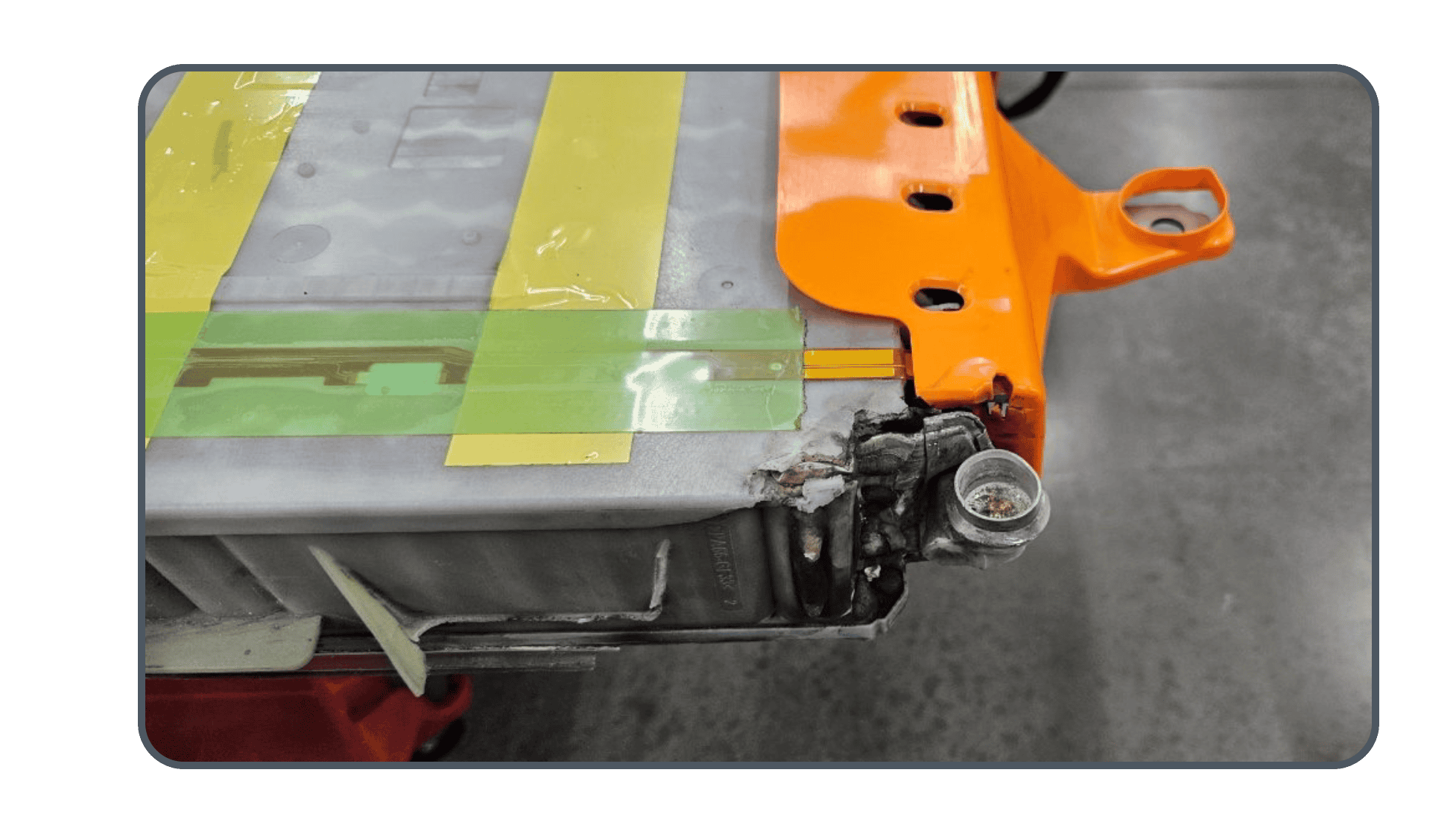
Furthermore, safety management in electric vehicles relies on highly sensitive systems capable of cutting off the high voltage in the event of a collision or malfunction. These systems are themselves powered by low voltage, which means that a simple failure of the 12-volt battery can disable essential safety functions.
Conclusion
The electrical architecture of modern vehicles is complex and interconnected, and any modification or repair can lead to unforeseen consequences if not performed according to best practices.
In this article, we have presented the basics of onboard electronics in modern vehicles, their protective mechanisms, and the main electrical failures, highlighting the specific characteristics of hybrid and electric vehicles. Following an accident, the role of the forensic expert is not limited to identifying a faulty component. At Origin, we analyze the electrical mechanisms involved, reconstruct the sequence of events, document physical evidence, and evaluate the interaction between low- and high-voltage systems. This approach enables us to establish a rigorous causal link, distinguish between an intrinsic failure and an improper repair or environmental factor, and inform the resulting technical and insurance decisions.
In a context where onboard electronics are playing an increasingly significant role and where hybrid and electric architectures are making analyses more complex, specialized expertise becomes an essential tool for understanding not only what happened, but why it happened—and for looking beyond the body panels by leveraging technological tools and analyzing imagery and data. This will be the subject of a future article!
To hire us, click here.
1 Smith, G. M. (July 18, 2025). “What is CAN Bus (Controller Area Network).” Dewesoft. https://dewesoft.com/blog/what-is-can-bus
2In this article, we prefer to use the term “e-fuse” to make it easier to read.
3Optifuse.(n.d.). “Type ANR Automotive Blade Fuse Standard.” https://d23ezng0vx028q.cloudfront.net/userfiles/documents/products/anr/anr.pdf
4Gluckman, D. (March 30, 2025). “The E-Fuse Kicks the Classic Blade-Style Fuse to the Curb.” Car And Driver. https://www.caranddriver.com/features/a64127857/the-e-fuse-kicks-the-classic-blade-style-fuse-to-the-curb/